
Industrial connectivity solutions
Cabur prepares and assembles your terminal block!
In addition to a custom design service, Cabury offers terminal blocks assembly based on your specifications.


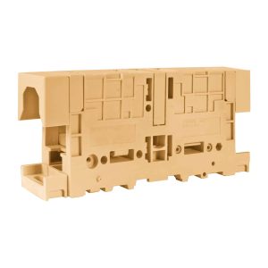
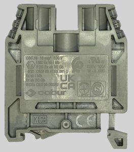
| Series | GPM |
|---|---|
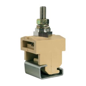
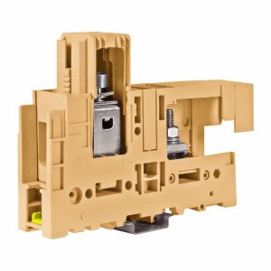
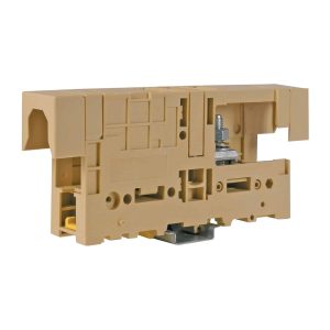
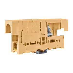
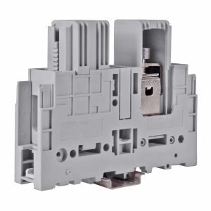
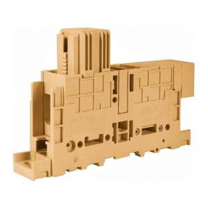
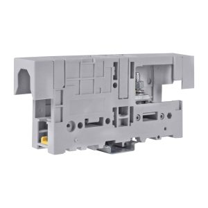
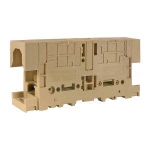
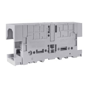
| Code | GP700GR |
| Type | GPM.240/BB/GR |
| Colour | Grey |
| HS code | 85369010 |
| TECHNICAL FEATURES | |
| Function/Type | Feed-through |
| Rated cross-section | 240 mm² |
| Connecting capacity | |
| Flexible wire | – |
| Rigid wire | – |
| Wire with ferrule - ferrule type | 40 mm – M12 (1) |
| Electrical characteristics according to IEC EN standard | |
| Maximum voltage AC/DC | 1000 V |
| Maximum current (rated cross-section) | 415 A nom./ 600 A max. |
| Caliber | – |
| Electrical characteristics according to ATEX directive and IEC Ex standard | |
| Maximum voltage AC/DC | 1000 V |
| Maximum current (rated cross-section) | 415 A |
| Operating temperature Min/Max | -40 °C / +80 °C |
| ensione impulsiva nom. / grado di inquinamento | 12 kV / 3 |
| Insulation stripping length | – |
| Tightening torque value (nom. / max.) | 14 / 21 Nm |
| Width (pitch) | 52 mm |
| Length | 250 mm |
| Height mounted on TH35-7.5/TH35-15/G32 | 89 / 96 / 93 mm |
| Height for panel mounting | – |
| Lenght mounted on panel | |
| Fixing distance between center | |
| Insulation material temperature index (EN 60216-1) | 130 °C |
| Plastic material | Polyamide UL94V-0 |
| ACCESSORIES | |
| Cross-connection | |
| Model A) | PFX/240/… (cod. PX24…) |
| Rated current carrying capacity IEC/ATEX | 415 A / 376 A |
| Marking | |
| Single marking tag | CNU/8/51 (cod. NU0851S) – CNU/10/61 (cod. NU1061S) |
| End bracket | |
| TH35 screw type | BT/3 (cod. BT003) |
| TH35 snap-fit type | BTO (cod. BT007) |
| TH35 and G32 snap-fit type | BTU (cod. BT005) |
| Mounting rail | |
| IEC 60715/TH35 | PR/3/… |
| IEC 60715/G32 | PR/DIN/… |
| APPROVALS AND MARKINGS |   |
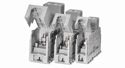


In addition to a custom design service, Cabury offers terminal blocks assembly based on your specifications.

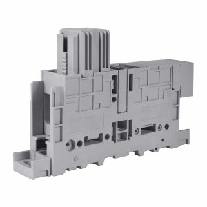
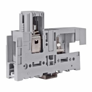
VPC.2/S is a 1.5 mm² screw terminal block for female connectors pitch 5.08 mm with aligned outputs.