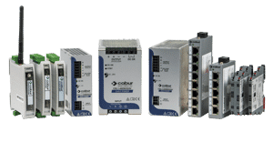


Solutions for renewable energy
E-mobility and Renewable Energy Solutions catalogue 2025
E-mobility and Renewable Energy solutions catalogue: an edition renewed even in name!
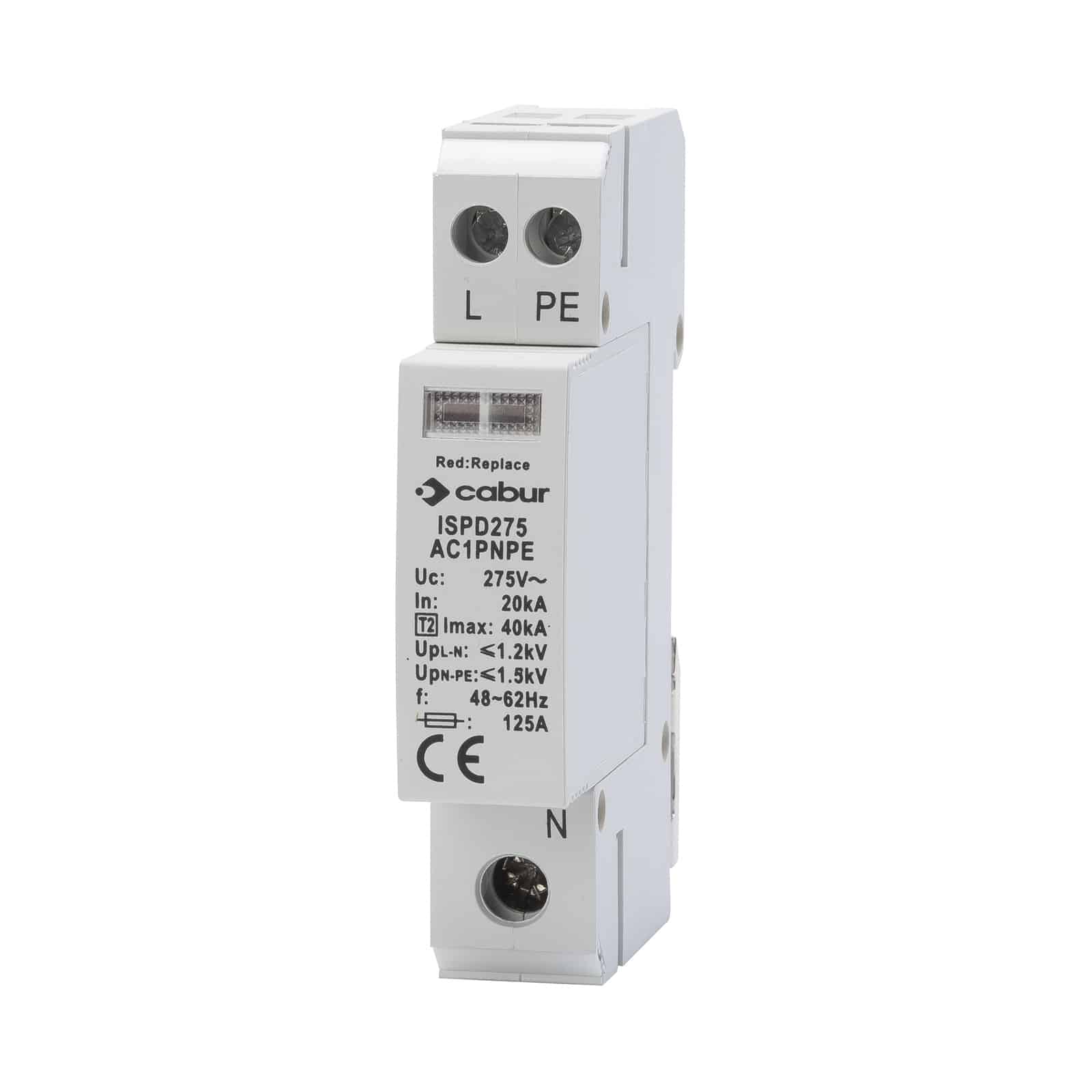
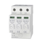
| Series | ISPD |
|---|---|
| Code | ISPD275AC1PNPE |
| Type | ISPD275AC1PNPE |
| HS code | 85354000 |
| TECHNICAL FEATURES | |
| Test class | II |
| Type of Network | TN, IT, TT |
| Nominal voltage Un | 220 – 230 (V) |
| Max. continuous voltage | 275 (V) |
| Working frequency | 50 – 60 (Hz) |
| Max. Discharge current (8/20μs) | 40 (kA) |
| Nominal discharge current (8/20μs) | 20 (kA) |
| Voltage protection level at In | 1.5 (kV) |
| Protection mode | L – N / N – PE |
| Isolation resistance | > 10² (MΩ) |
| Response time | ≤ 25 (ns) |
| Recommended back-up fuse | 125 (1) (A) |
| Max. cables section | 25 (mm²) |
| Mounting Guida TH35 | Yes |
| Working temperature | -40…+70 °C |
| Protection degree | IP20 |
| Housing material | PPO |
| Inflammability class | UL94-V0 |
| Fault indicator | |
| Red LED | Fail |
| Dimensions (LxHxD) | 18x90x66 |
| Quantity / Package | 1 piece |
| ACCESSORIES | |
| APPROVALS AND MARKINGS |

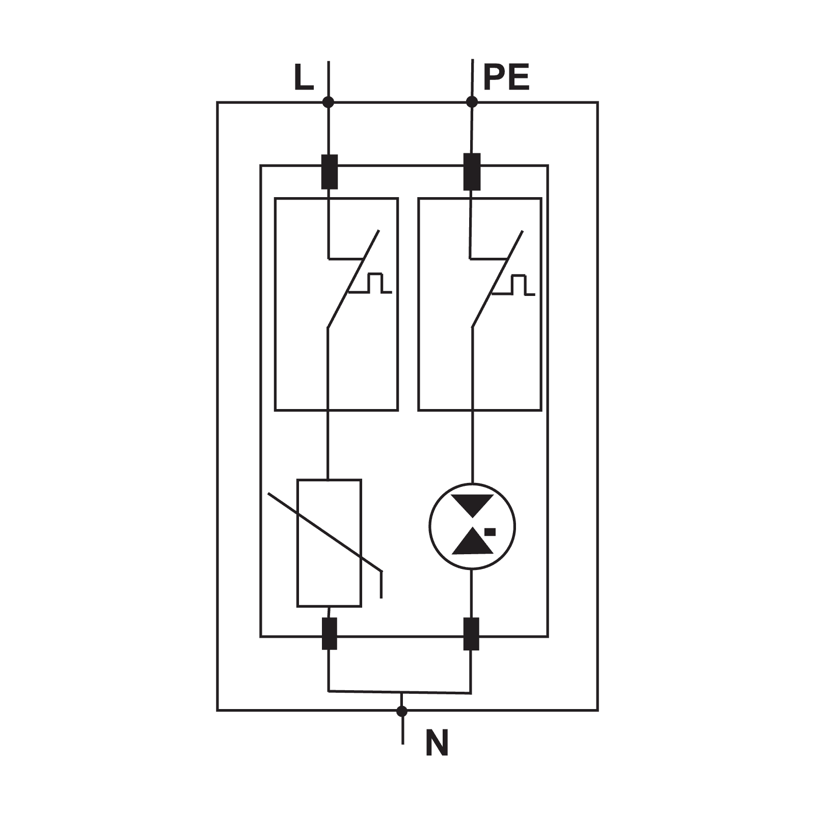
Surge protection devices (SPD) prevent sudden electrical surges induced to the PV array by the earthed network and conducted to the AC power supply network or signal line from damaging the electronic equipment.
The surge protection device Cabur products are composed by varistory and gas cartridge for the AC protection, and Y configuration at 600VDC and 1000VDC for DC protections.
In the case of transitory power surges, the only way to protect equipment is to limit the difference in voltage between the various conductors that exit/enter the device. For this reason, in PV systems the surge protection must always be installed on both the AC and DC sides, so as to guarantee equal voltage between all the various system conductors, both in the case that the surge arrives from the PV array or from the AC or earthed network.
In the case of a power surge on the PV array, the DC side SPDs create an instantaneous short-circuit between the positive, negative, and earthed conductors, establishing a transitory voltage equilibrium. Hence the three conductors on the DC side of the inverter rise to thousands of V, but as the SPDs limit the difference in voltage between the three conductors to 4kV, no malfunctions will occur on the DC side of the inverter, which will have a resistance to impulse power surges greater than 4kV.
Alone, however, this is insufficient to protect the inverter from malfunctioning, because if the three conductors on the DC side rise to 10kV and on the AC side there are no SPDs able to create transitory voltage equilibrium with the DC side, then the DC side at 10kV will “see” the 230-400 AC exiting from the inverter as a lower voltage to which it can discharge through the insulation and/or components of the inverter, destroying them. Similarly, the same thing would occur if the power surge occurred on the AC side. The concept of equal voltage requires the use of SPDs on all conductors that exit and enter the inverter, because only by limiting the difference in voltage between the
AC and DC sides and the earthing, that is to say within the surge levels that the device is able to support, can destructive surges to the insulations or components be avoided.
The varistor, the active element of the SPD, is a component that is able to support a limited number of discharges. It can still short circuit if subjected to a discharge that exceeds its max Isc, or if it is subjected
to multiple discharges below its max Isc, gradually deteriorating its performance. Under these conditions, its resistance, which normally is in tens of MΩ, will decrease to a few hundreds/tens of Ω, the varistor will overheat due to the passage of current between the line and the earthing, and it can catch fire.
Regulations regarding Test Class II SPDs requires them to be provided with a device which disconnects them from the line at the end of their useful life. The device consists of a contact in series on the side of the line which has its ends welded airtight, one of which is spring-loaded. When the overheated varistor exceeds the fusion temperature of the seal, the spring-loaded conductor disconnects, opening the contact and disconnecting the varistor from the line, thereby preventing damage. In modern SPDs, created for us on AC lines, in which the disconnection device is able to eliminate the arc, during the pass to zero of the AC current, consequent to the opening of
the broken varistor through which the short L/earthing current passes. In PV systems the varying conditions make the automatic disconnection task of the SPDs more difficult. DC voltages from 500 to 1,000 V and no pass to zero for the voltage/current makes interruption of the arc between the contacts at entry more difficult, because the air and surface distances designed for AC are not sufficient to guarantee disconnection power
for the arc in DC. The problem is solved by using three varistors set up in a “Y” formation. With the Y set up, the discharge is divided into three varistors instead of the two found in the classic formation. This makes it much less likely that one of them will malfunction. Nevertheless, in the case of a shortcircuit in one of the varistors, in the circuit between the Line and the earthing, once the surge has passed, the second intact varistor returns to the resistance MΩ, cutting off the current to the contact on the malfunctioning varistor.
Cabur does not recommend the use of earthed gas discharge devices on the DC side, because while they are able to ensure insulation in terms of earthing, in the case of a short or semishort circuit to a varistor, the gas discharge device would not be set off by the DC voltage, meaning that the string Isc would pass through the varistor, and it could catch fire.
E-mobility and Renewable Energy solutions catalogue: an edition renewed even in name!

These include twelve new models, six for the ISA range and six for the ISB range.

The project consists of the installation of 12 Cabur wall-mounted charging stations for electric and hybrid cars, along the wall adjacent to the parking stalls and another 9 on poles fixed to the ground, placed under a well-lit shelter.