Solutions for automations and control
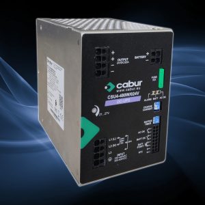
New Cabur power supply with integrated DC-UPS
Ideal for applications where service continuity is essential: industrial automation, process control, alarm systems, and remote monitoring.
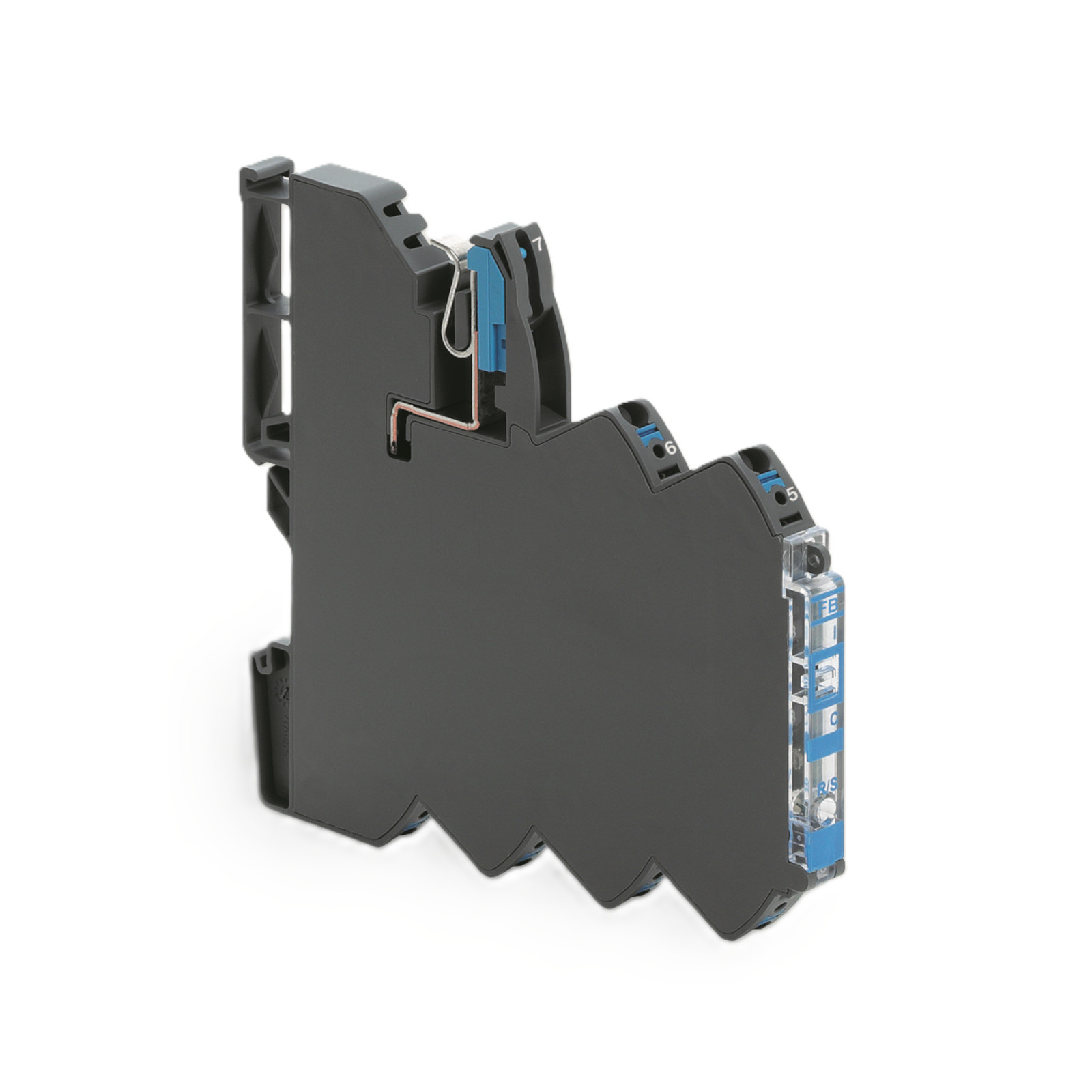
| Series | CEP |
|---|---|
| Code | XCEPD1 |
| Type | CEP-D1 – |
| HS code | 85361010 |
| INPUT TECHNICAL DATA | |
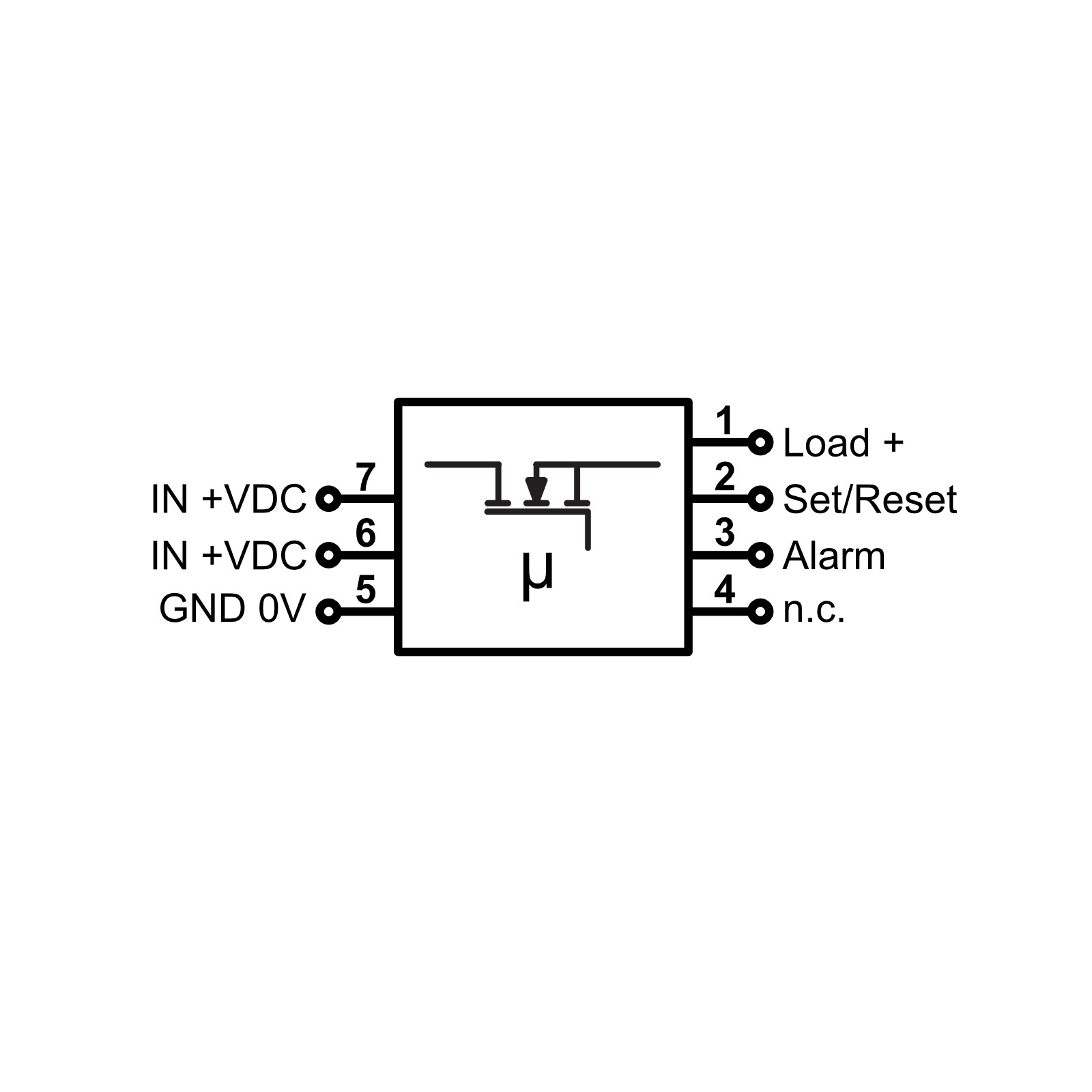
| Input rated voltage | 12-24 Vdc |
| Input voltage range | 10…30 Vdc |
| Input current | 10 A |
| OUTPUT TECHNICAL DATA | |
| Version | 1-channel |
| Output voltage range | 12-24 Vdc (voltage drop max. 215 mV/10 A) |
| Continuous current | 1…10 A DC adjustable in 1 A step |
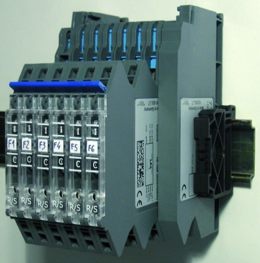
| Max system current | 40 A DC with XCEPRCC distribution bar |
| Curve di intervento | Fast (1), medium (2), slow 1 (3), slow 2 (4), slow 3 (5) |
| Max connectable output capacity | 10,000 μF |
| Protection | electronic, against reverse polarity |
| Controllo remoto ON / OFF | DC 12/24 V acc. to EN 61131 OFF: <800 ms ON: >1 s |
| Status indication | Green LED: constant = OK, flashing = Iout at 90% of nominal, red LED: constant = output manually switched off, flashing slowly = overcurrent, flashing quickly = error |
| Alarm contact | open collector transistor (overcurrent status) |
| GENERAL TECHNICAL DATA | |
| Operating temperature range | –25…+50°C |
| Safety Standard | — |
| EMC Standard | EN 61000-6-2, EN 61000-6-3 |
| Protection degree | IP 20 |
| Connection terminal | 2.5 mm² push-in |
| Housing material | UL94V-0 plastic material |
| Dimensions (LxHxD) | 8.1×107.4×116.0 mm |
| Approximate weight | 70 g |
| Mounting information | Any position, side-by-side individually or in a bank with distribution bridge |
| ACCESSORIES | |
| Mounting rail (IEC60715/TH35-7.5) | PR003, PR903, PR005, PR905 |
| Marking tag | NUWDU50S (100 tags) |
| Ponte di alimentazione | XCEPRCC (1 m) XCEPRCC04 (for 4 modules) XCEPRCC08 (for 8 modules) XCEPRCC16 (for 16 modules) |
| Supporto ponte di alimentazione | XCEPSS |
| Copertura ponte di alimentazione | XCEPRCP |
| Ponte segnali | XCEPBCR (8 poles red) XCEPBCB (8 poles blue) |
| APPROVALS AND MARKINGS |


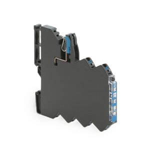
Ideal for applications where service continuity is essential: industrial automation, process control, alarm systems, and remote monitoring.

The new range is part of the Easy Power series and represents an advanced solution in the field of industrial power supplies. It is designed for standard applications that require an excellent price/performance ratio, small footprint and high power density, an extended operational temperature range and high energy efficiency.

Discover the latest news from Cabur’s Automation and Control Solutions line!