


EVENTS and PROMOTIONS
Happy summer holidays 2025 by Cabur and Elettra!
Cabur will be closed for the summer holidays from August 4 until August 22, 2025 included.
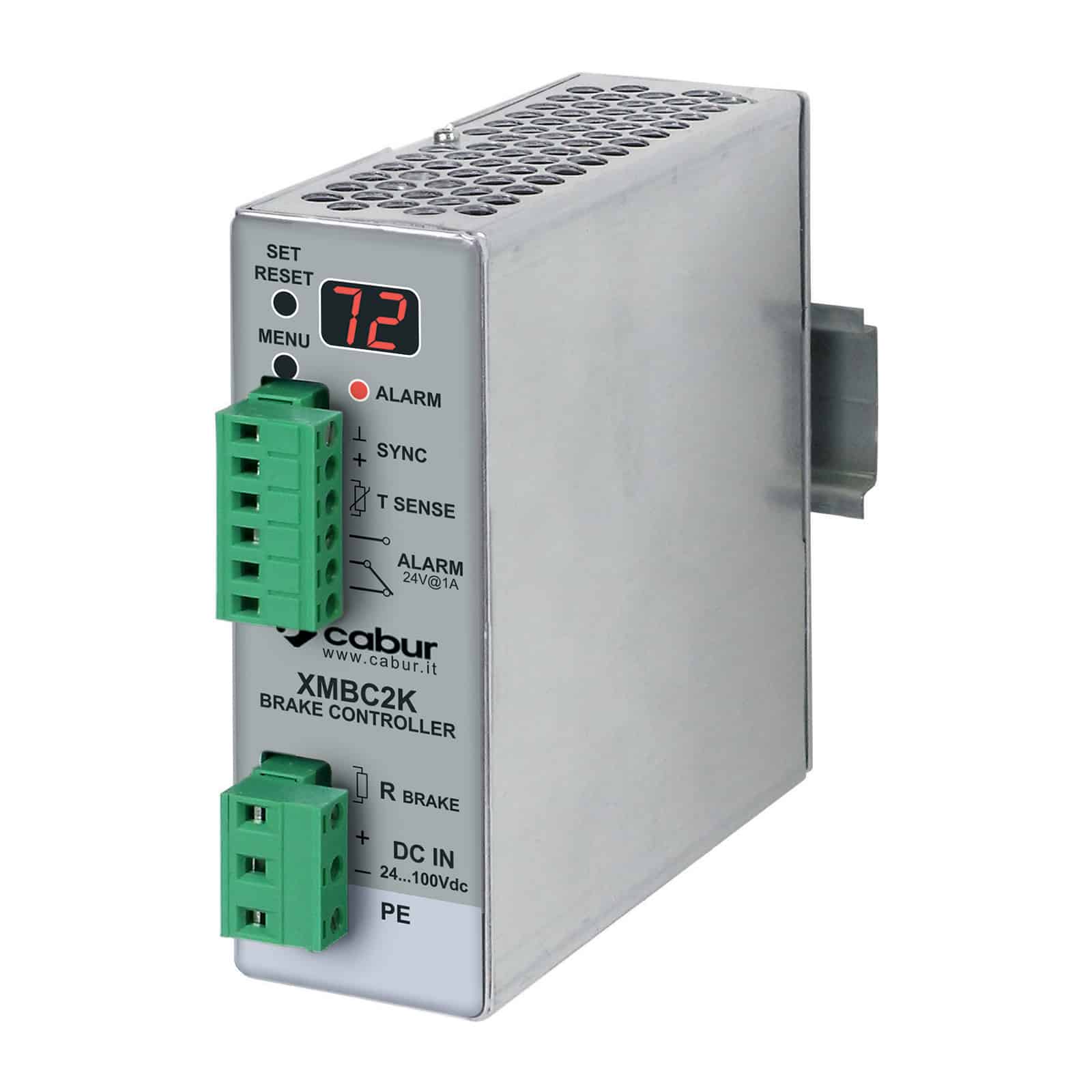

MBC2K is a microprocessor-controlled device designed for braking DC bus-powered engines. It is activated by the surge generated by the engine when its drive requires braking.
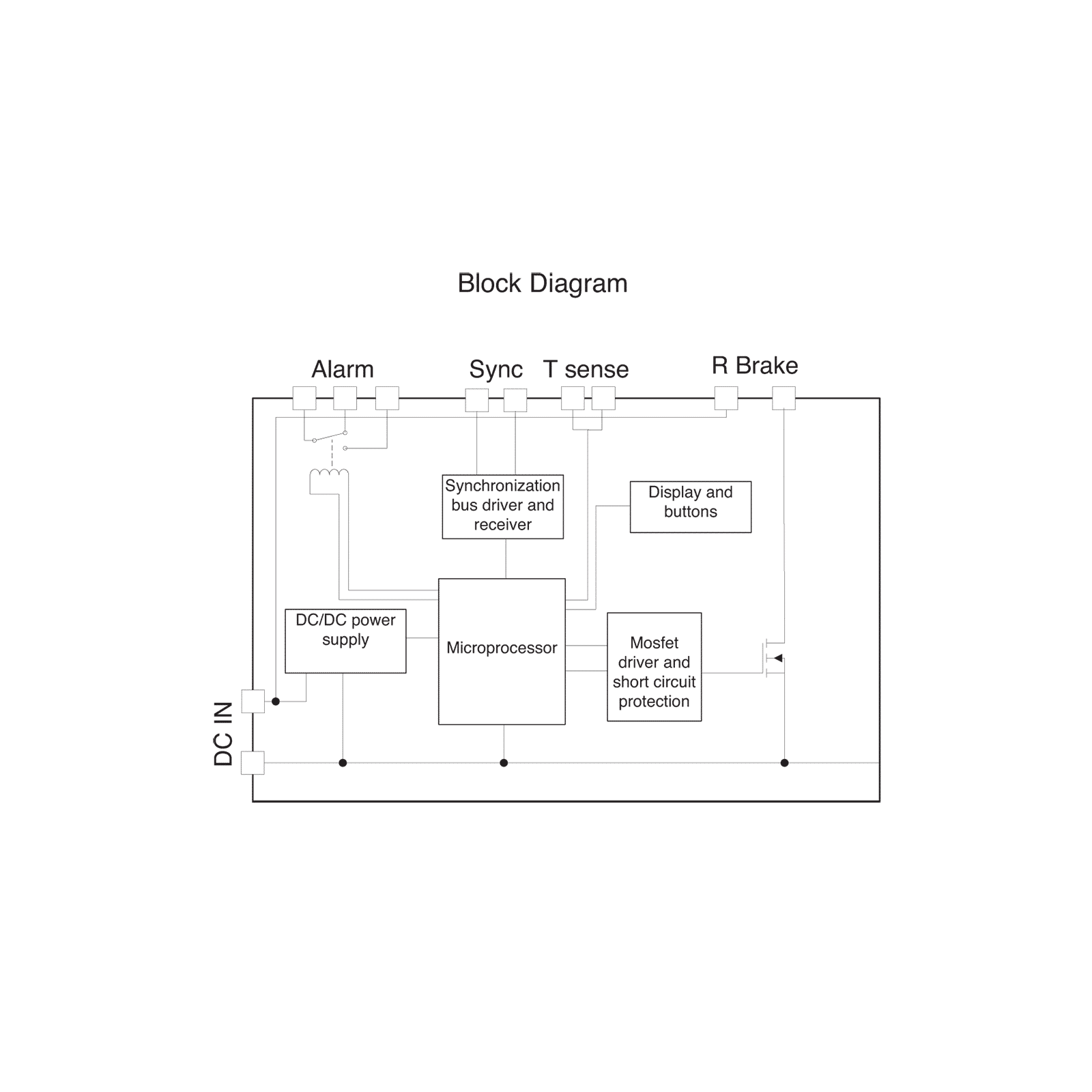
When the MBC2K is connected on the DC bus powering the engine drive (see diagram in fig. 1), the device activates automatically
when the DC bus voltage exceeds the set threshold and transfers the power generated by the engine to the braking resistor,
where it is dissipated. MBC2k is equipped with protection against short circuit, overload and over temperature in order to guarantee reliable operation. MBC2K can be connected to any DC bus power supply with a voltage within 24 and 100 Vdc. The simplified
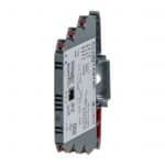
application is illustrated in the block diagram in Figure 1, the front view of the unit with all controls and functions is shown in Figure 2. CONNECT up to 4 units in parallel to increase the peak braking power up to 8 KW. MBC2K also has a 7-segment display and an LED for instantly viewing the DC bus voltage (accuracy +/- 1 V) which helps the user during set-up and in displaying error messages.

MBC2K setup
The MBC2K unit must be set-up prior to operation.
The menu comprises three pages, navigable using the MENU button;
The values shown can be adjusted by pressing the SET/RESET button.
Active protections
The MBC2K integrates active protections to ensure stable and reliable operation under normal use conditions. When it detects a fault, MBC2K turns itself off to prevent an uncontrolled flow of current through the braking resistor.
Fault status is indicated by the alarm LED flashing continuously.
And the integrated alarm relay allows the status of the module to be checked remotely.
To help the user understand which defect has occurred, an error code is shown on the 7-segment display.
Connect up to 4 MBC2K units in parallel
Up to 4 MBC2K units can be connected in parallel to increase peak braking capacity to 8 KW. Each unit is capable of braking 2 KW of peak power, for which each unit requires its own braking resistor. To set up this configuration, MBC2K is equipped with a bus that is used to synchronise the operation of all connected units (up to 4 max.). The principle of operation is based on one MBC2K unit configured as a Master and the other MBC2K units (up to 3) configured as Slaves.
The Master measures the DC bus voltage and decides when to insert the braking resistors into the circuit, sending a command on the synchronisation bus. When the Slave units connected to the synchronisation bus receive the command from the Master unit, they insert their braking resistor into the circuit. When MBC2K is configured in Slave mode, all of its protective circuits remain operational.
 MENU: Used to enter set-up mode and to navigate through the menu pages.
Cabur will be closed for the summer holidays from August 4 until August 22, 2025 included.

Cabur’s 2024 Sustainability Report demonstrates the company’s concrete performance in environmental matters and in the areas of personnel management, training and welfare, as well as in its relationships with customers and the local community.

The new range is part of the Easy Power series and represents an advanced solution in the field of industrial power supplies. It is designed for standard applications that require an excellent price/performance ratio, small footprint and high power density, an extended operational temperature range and high energy efficiency.