€299.60 + VAT
In stock
In stock
| Code | XSWET5PU |
|---|---|
| Type | SWET-5PU – |
| HS code | 85176200 |
| Version | 5 – RJ45 unmanaged |
| Interface | |
| Number and type of interface | 5 RJ45 ports |
| Connection method | Auto negotiation, Full/Half duplex mode, auto MDI/MDI-X connection |
| Transmission speed | 10/100 Mbps |
| MAC table size | 2K |
| Status indication | Power, Link/Speed, Link /Activity |
| GENERAL TECHNICAL DATA | |
| Power supply voltage | 12-24 Vac/dc (12…36 Vdc / (10…24 Vac) |
| Current consumption | 170 mA |
| Operating temperature range | -10 a 60˚C |
| Ambient temperature range (storage) | |
| Standards | IEEE802.3, 802.3u, 802.3x |
| Safety Standard | EN 62368-1 |
| EMC Standard | EN61000-4-2, EN61000-4-3, EN61000-4-4, EN61000-4-5, EN61000-4-6, EN61000-6-2 |
| Overvoltage category /pollution degree | I / 2 |
| Protection degree | IP 30 |
| Connection type | 1.5 mm² (screw) |
| Series | |
| Housing material | metallic |
| Dimensions (LxHxD) | 25×100×75 mm |
| Approximate weight | |
| Mounting information | on a rail, side by side |
| APPROVALS AND MARKINGS |    |
| ACCESSORIES | |
| Mounting rail (IEC60715/TH35-7.5) | PR/3/AC, PR/3/AC/ZB, PR/3/AS, PR/3/AS/ZB |
| Mounting rail (IEC60715/TH35-15) | PR/3/PP, PR/3/PP/ZB, PR/3/PA, PR/3/PA/ZB |
For further information see PDF catalog

They convert electrical signals generated by sensors which take physical measure-ments such as temperature (thermocouples and PT100 resistance thermometers), frequency (proximity, contacts, photocells), current (TA, Hall sensors), resistance (potentiometers), voltage, pressure, level, etc. into standardised electrical signals, adapting them to PLC, DCS and industrial PC (control) outputs, or they convert a given analogue signal into a different one, adapting it to control inputs/outputs or allowing for long-distance signal transmission without interference by means of galvanic separation (fig. 1).
Adaptation between sensor output signal and control input signal

Long-distance signal transmission
Voltage signals can reach a max. distance of 10-20 m, beyond which they lose reliability and become highly sensitive to induced and ground-derived interference, therefore in order to transmit to distances beyond 20 m a voltage signal must be converted into a current signal and galvanically separated (fig. 2).
Current signals can surpass a transmission distance of 300 m and are less sensitive to induced interference. The long-distance transmission of a current signal requires galvanic separation.

Galvanic signal separation (signal isolation):
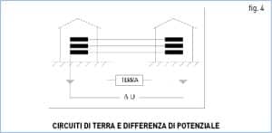
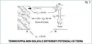
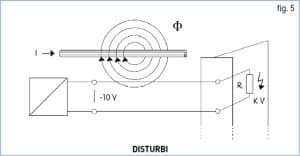 Galvanic separation is necessary when:
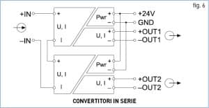 Connection of analogue converters in series and in parallel
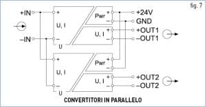 In case of voltage signals, the converter input will be connected in parallel (fig. 7


Copyright © Cabur srl Sede legale Località isola Grande, 45 – 17041 Altare (SV) – Italia – Tel. 019-589991 – Fax 019-58999233 – E-mail: info@cabur.it
Cap. Sociale: €2.000.000 Int. versato – Reg. Soc. Trib. Savona N° 4635 – C.C.I.A.A. N° 27269- Export N° SV 000532 – P.IVA e Cod. Fisc.: 00100760099
DISCLAIMER Cabur Srl may change and update any document available online without any obligation to inform users. Only cabur.it and cabur.eu domains are registered and maintained by Cabur srl. Cabur has no responsibility for contents published on sites under the same name, with different extensions from .it and .eu
for technical support
+39 019 58999.219 customercare@cabur.it
for commercial support
+39 019 58999.609 vendite@cabur.it
from monday to friday 8:30-12:30 13:00-17:00