


EVENTS and PROMOTIONS
Happy summer holidays 2025 by Cabur and Elettra!
Cabur will be closed for the summer holidays from August 4 until August 22, 2025 included.
| Series | CON |
|---|---|
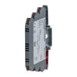
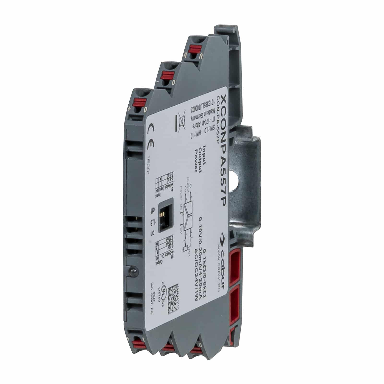
| Code | XCONPA557P |
| Type | CON-PA-557P |
| INPUT TECHNICAL DATA | |
| HS code | 85043129 |
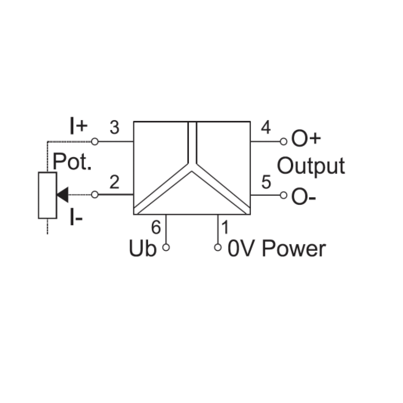
| Signal type IN | potentiometers |
| Input range IN | 0…1 kΩ / 0…6 kΩ |
| Input impedance IN | 1 MΩ |
| Parametrization IN | DIP switch |
| OUTPUT TECHNICAL DATA | |
| Signal type OUT | analogue |
| Output range OUT | 0…10 V / 0…20 mA / 4…20 mA |
| Maximum output signal OUT | 16 V (current output) / 5 mA (voltage output) |
| Load impedance OUT | >2 kΩ (voltage output) / < 700 Ω (current output) |
| Ripple | <20 mV |
| Status indication | LED |
| Parametrization OUT | DIP switch |
| GENERAL TECHNICAL DATA | |
| Power supply voltage | 24 Vac/dc (19.2…26.4 Vdc / 19.2…26.4 Vac) |
| Current consumption | 13 mA (24 Vdc) / 22 mA (24 Vac) |
| Accuracy | 0.3% FSR (23°C) |
| Linearity error | ±0.1% FSR |
| Temperature coefficient | <150 ppm / K FSR |
| Transmission frequency | 10 Hz 3dB |
| Operating temperature range | -25…+60°C |
| Insulation | 2.5 kVac / 60 s |
| Insulation type | 3-way (IN / OUT / power) |
| Standard approvals | EN 60947-5-1 |
| Overvoltage category / pollution degree | II / 2 |
| Protection degree | IP 20 |
| Connection terminal IN / OUT | 2.5 mm² / 2.5 mm² (push-in) |
| Housing material | UL94V-0 plastic material |
| Dimensions (LxHxD) | 6.2x93x73 mm |
| Approximate weight | 29 g |
| Mounting information | on a rail, side by side |
| ACCESSORIES | |
| Mounting rail (IEC60715/TH35-7.5) | PR/3/AC, PR/3/AC/ZB, PR/3/AS, PR/3/AS/ZB |
| APPROVALS AND MARKINGS |

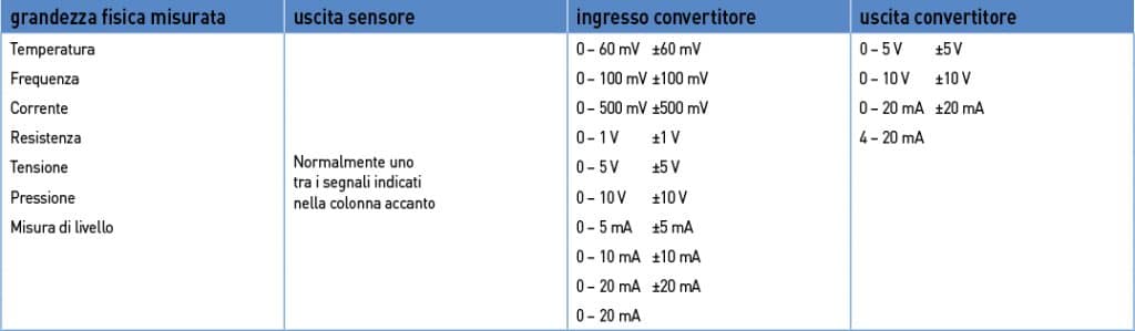
They convert electrical signals generated by sensors which take physical measure-ments such as temperature (thermocouples and PT100 resistance thermometers), frequency (proximity, contacts, photocells), current (TA, Hall sensors), resistance (potentiometers), voltage, pressure, level, etc. into standardised electrical signals, adapting them to PLC, DCS and industrial PC (control) outputs, or they convert a given analogue signal into a different one, adapting it to control inputs/outputs or allowing for long-distance signal transmission without interference by means of galvanic separation (fig. 1).
Adaptation between sensor output signal and control input signal
Long-distance signal transmission
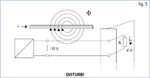
Voltage signals can reach a max. distance of 10-20 m, beyond which they lose reliability and become highly sensitive to induced and ground-derived interference, therefore in order to transmit to distances beyond 20 m a voltage signal must be converted into a current signal and galvanically separated (fig. 2).
Current signals can surpass a transmission distance of 300 m and are less sensitive to induced interference. The long-distance transmission of a current signal requires galvanic separation.

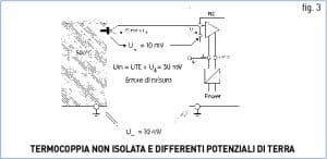
Galvanic signal separation (signal isolation):
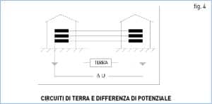
 Galvanic separation is necessary when:
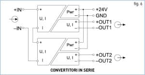 Connection of analogue converters in series and in parallel
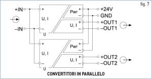 In case of voltage signals, the converter input will be connected in parallel (fig. 7
Cabur will be closed for the summer holidays from August 4 until August 22, 2025 included.

Cabur’s 2024 Sustainability Report demonstrates the company’s concrete performance in environmental matters and in the areas of personnel management, training and welfare, as well as in its relationships with customers and the local community.

The new range is part of the Easy Power series and represents an advanced solution in the field of industrial power supplies. It is designed for standard applications that require an excellent price/performance ratio, small footprint and high power density, an extended operational temperature range and high energy efficiency.